This is part of a series originally published on Britmodeller.com. You can view the original article HERE.
Placing the Exhausts
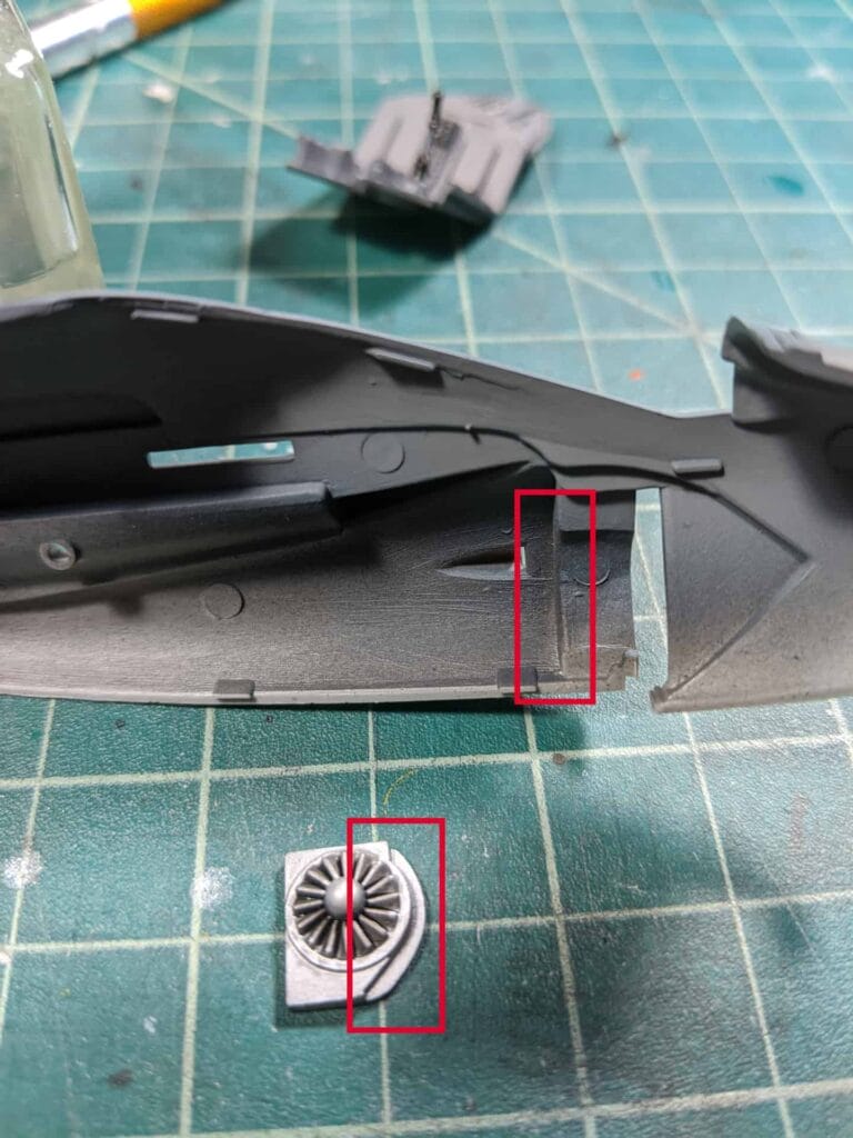
Moving along, here we have the intake and exhaust fan blades painted up in silver with an enamel wash applied. Instructions called for the (right) piece to be painted black and the (left) piece painted white outside the fan blade. I’ll skip this as you won’t see it once built up – even with a pen light.
Ok, so fitting the fan blades. Not too difficult – the curved edge of the blade piece needs to fit flush the fuselage part outlined in red. It doesn’t fit flush so it takes a bit of play to get in right. Straightness doesn’t matter too much as the fan blade is…well..round so it looks fine either way.
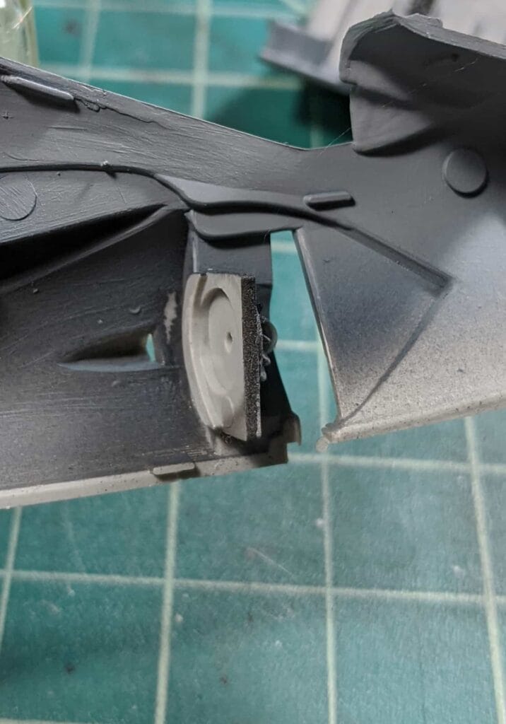
Here it is inserted.
Inserting the Cockpit
OK, buckle up because the cockpit fit is a disaster.
First, the shape of the stern area of the pit does not fit flush with the closed up fuselage halves. You’ll see this later once it’s inserted.
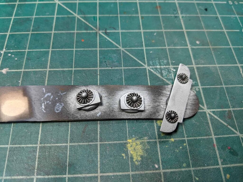
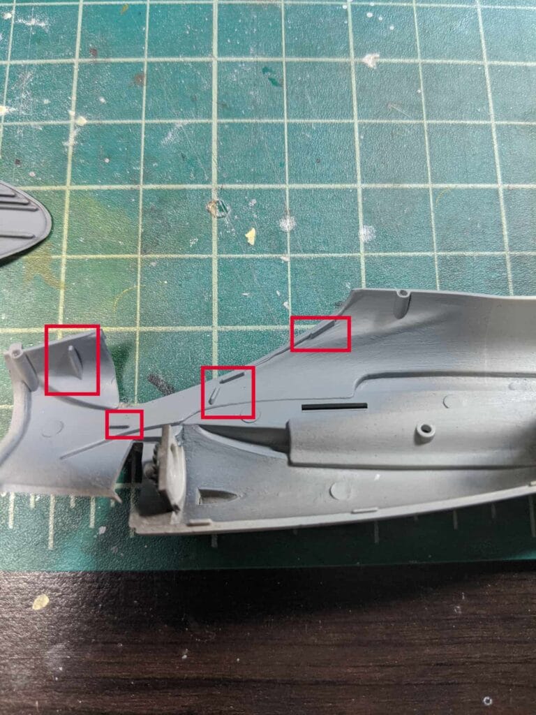
Next, the cockpit locator brackets (highlighted in red) do not fit the cockpit. They’re essentially slapped on the fuselage and the Italeri engineers are saying it goes around here…somewhere. So there’s a lot of dry fitting involved as it can shift around easily.
But wait, there’s more! The instrument panel, since it doesn’t fit to the cockpit like most normal aircraft, fits to the fuselage with a crappy little locator bump (in red – farthest left). And I’m sure you can guess…it doesn’t fit the contour of the IP.
So here’s what the instructions call for. Glue both the IP and cockpit to the right side fuselage half. So one both are on mate it with the other fuselage half. Good luck…no seriously…good luck.
Here’s what I did after hours of trial and error:
- Mate the fuselage halves and secure with tape (dry fit essentially).
- Insert cockpit and perform laparoscopic surgery to get it to sit right. Remember those locator “bumps”? Well since they are so shallow and not in the precise locations the cockpit will not stay in place. It has a tendency to either droop up/down or lean left/right. I hope you left your patience on your workbench.
- Glue cockpit once secure and glue fuselage together.
- Insert IP through the cockpit opening and adjust, again using laparoscopic surgery, through the open nose area of the fuselage.
The above method is the only way I found to get the cockpit and IP to sit straight and secure. If you follow the kit instruction is GUA-RAN-TEE either your cockpit or IP will be crooked. And yes, it will be noticeable.
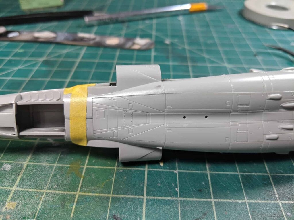
Here’s the cockpit inserted. After all is said and done it’s straight and it’s glued down. But you can see the gaps and ridges left behind. This will need lots of sanding and putty.
Here are locator bumps:
Here’s the cockpit inserted. After all is said and done it’s straight and it’s glued down. But you can see the gaps and ridges left behind. This will need lots of sanding and putty.

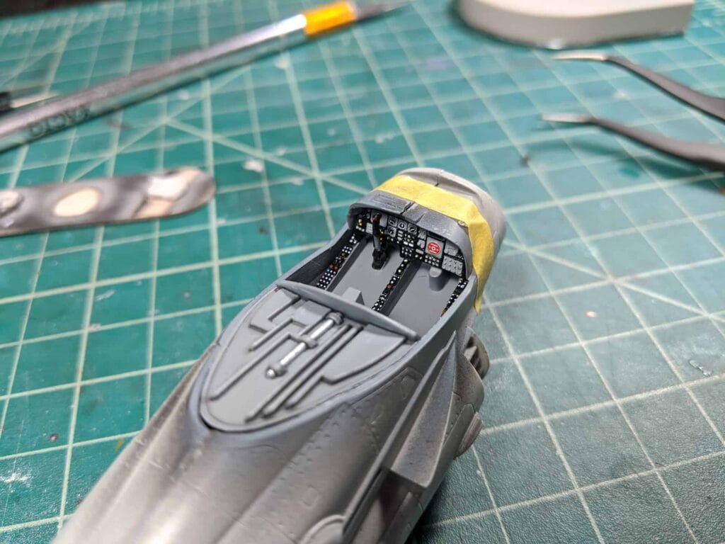
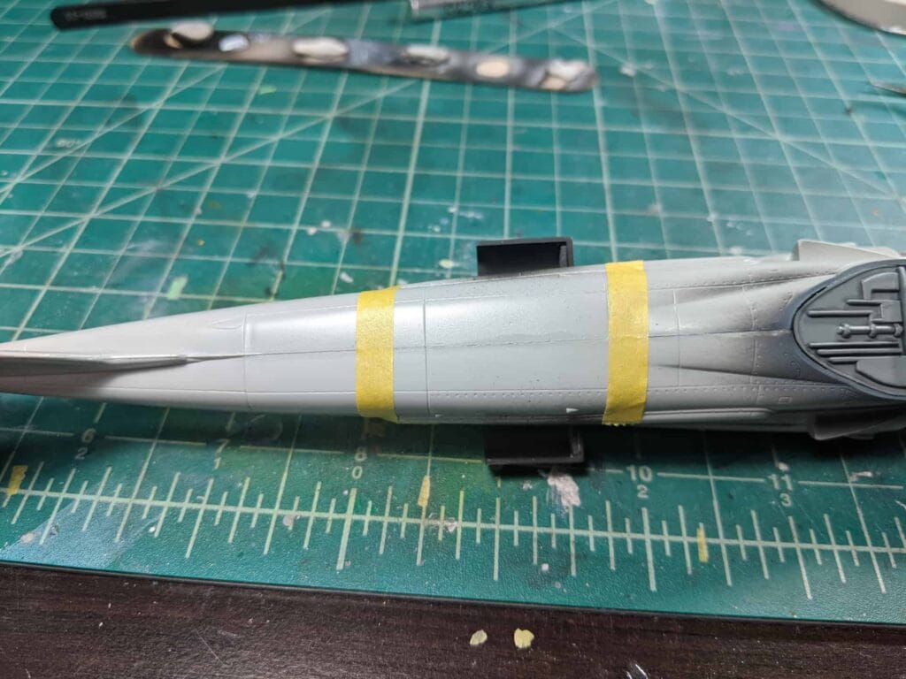
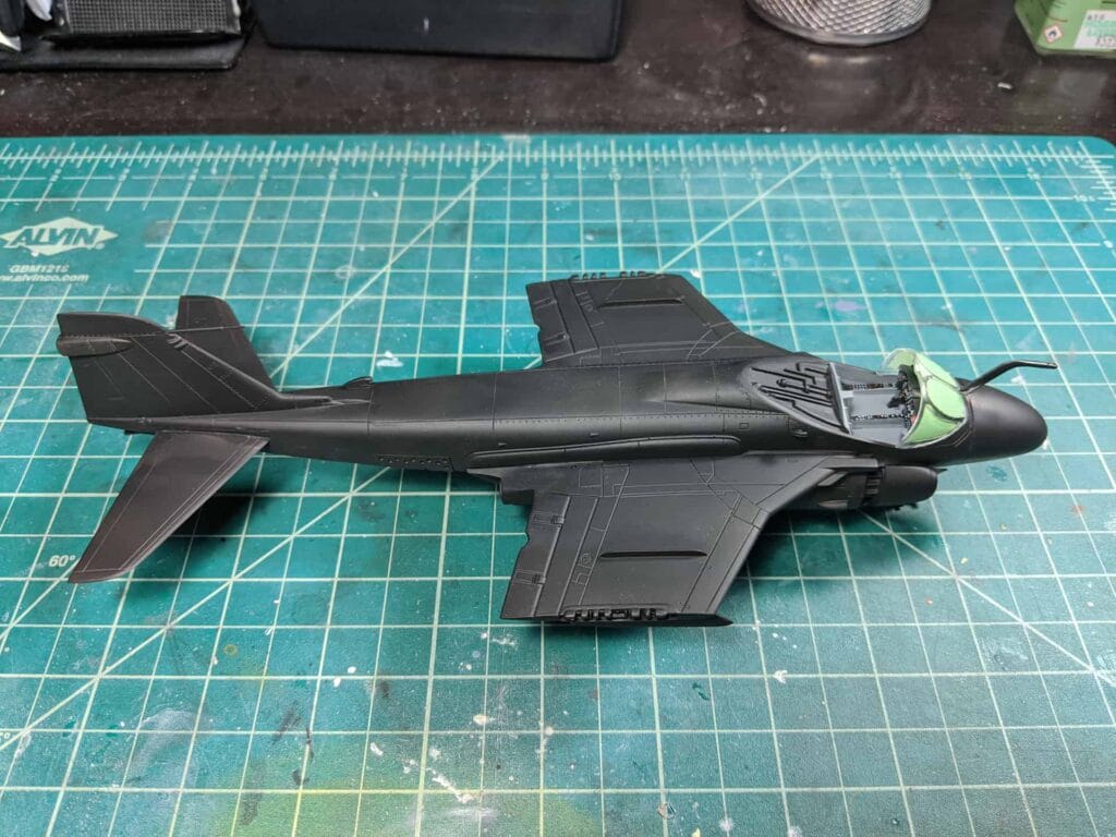
Finally here is the fuselage closed up and the bottom panel piece attached. On the top of the fuselage is about what you expect from standard kits in terms of seam lines. That one should clean up fairly easily.
On the bottom though – the panel leaves a lot to be desired. It’s biggest issue being the panel lines do not line up!! So after sanding and filling they will need to be rescribed to line up appropriately with the rest of the fuselage. I’m going to get my money’s worth out of the Infini sanding sponges I have – that’s for sure.